Notifications
Clear all
Software
1
Posts
1
Users
0
Reactions
2,228
Views

Topic starter
30/08/2023 1:24 pm
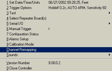
Channel Remapping
Channel remapping allows you to change:
-
the order of channels on each analog spread
cable that connects to the Geode
- reorder the Geode boxes.
You would use this option if your cables were wired
opposite to the default order normally used in
Geometrics wiring, if you wished to turn your line
around to have the low channels at the opposite end, or if your cables had a wiring error. Channel
remapping is also often necessary when using more that a single network cable.
Default cable wiring of Geometrics seismographs
Default order is defined as the natural electrical order in which channels are oriented when the
system first powers up before remapping. Refer to Section 3 under Connector Wiring that
discusses standard wiring configurations. You may have requested a custom wiring configuration
from Geometrics. If you are confused about your wiring, contact the factory and refer to the serial
number and job number.
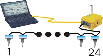
Geode cables are typically wired in a ‘high-side
configuration’, meaning that the Geode connects closest
to the highest numbered channel on the analog cable. The
149
figure above shows this configuration for a single box system, with 24 channels.
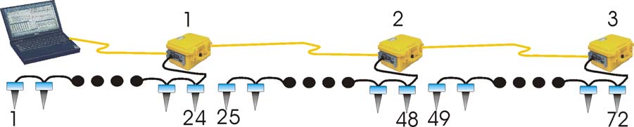
Multiple Geodes
The following diagram shows a default single digital line (one network card) system with 3
Geodes. Note that Geode one is always closest to the controller in a default configuration.
Multiple Network Lines
The next diagram below shows a default configuration with two digital lines (two network cards)
with the controller positioned in the middle. Line 1 is on the left and line 2 is on the right. One
might use two lines to increase data throughput to reduce time between shots. Like the
configuration above, the Geodes are numbered starting closest to the controller. The seismic
controller software labels all of the channels contiguously even though they are on two separate
digital lines. However, if the lines are collinear, the first line will have the channels ordered
backwards. This can be easily rectified with the remapping feature.

There are two ways of remapping channels: automatic mode and manual mode. Automatic mode
settings are listed on the top of the remapping dialog box, and manual mode on the bottom.
Automatic Channel Remapping
Automatic channel remapping allows you to reverse
either the order of the Geodes on the line, or reverse the order of the channels on the spread cable.
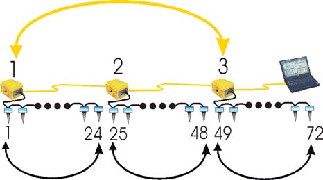
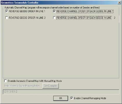
The above diagram shows the result after both channels and Geodes have been reversed,
renumbering the line so that low channels start on the left hand side and increase towards the
right. In the dialog box, the automatic remapping boxes referencing line 2 remain unchecked,
since the default orientation on line two was correct.
Manual Channel Remapping
Channels can be remapped on an
individual basis using the Manual Map
Mode. Select the appropriate check box,
and enter the order in which you would
like the channels that differs from the
default order. You can specify individual
channels separated by a comma (1, 3, 4, 6
etc) or a range of channels (1-13, 24-14
etc).
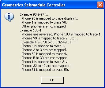
For example, if you wanted the channels
ordered backwards on a 24-channel
system, you would enter 24-1. If you
wished to reverse the order of channels 1-
12 in a 24 channel system, you would type
12-1, 13-24. Other examples are shown opposite, and are available by pressing the See Examples
button on the remapping menu.