Snell’s Law describes quantitatively how wave fronts refract or "bend" at boundaries between contrasting velocities. You've seen it manifest in light waves by the apparent bend of the straw in your glass of water; light travels slower in water than it does in air. Refraction is well illustrated using Huygen's Principle. Consider a wave front (for our purposes, a seismic one) emanating from a point energy source, as shown in the animation above. For simplification, assume we are far enough from the energy source that the wave front is essentially planar, and is approaching an abrupt change in seismic velocity:
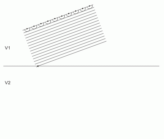
Applying Huygen's Principle, we see that after time t, the plane wave has advanced a distance d equal to the radii of a series of spherical wave fronts emanating from the plane wave:
The radii of the spheres, i.e., the distance the plane wave travels in time t, is equal to V1t. The tangent to the spherical wave fronts is the new position of the plane wave. The planar wavefront continues at velocity V1. Again applying Huygen, we see that "every point on the wave front" (see discussion of Huygen above) includes the points where the wave front intersects the velocity boundary:
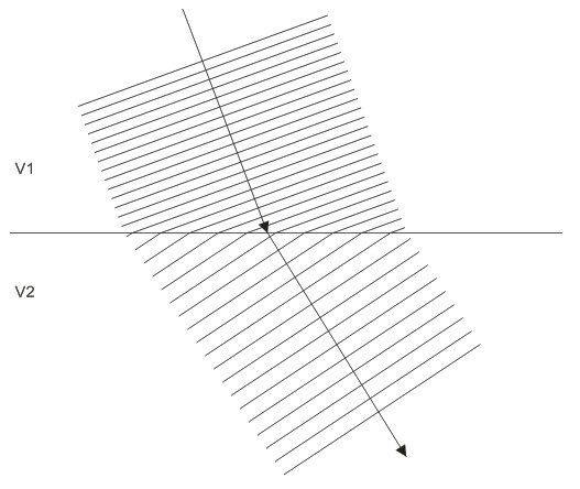
As the planar wave front advances, the velocity boundary becomes a new source of spherical wave fronts expanding at V2. Hence, part of the plane wave (the tangent to the spherical wave fronts emanating from the velocity boundary) is now traveling at V2. Note that within V2, its direction of advance has changed. This is because in V2, which is higher than V1, Huygen's spheres grow faster during time t.
The refracted wave front continues in the new direction until another velocity boundary is encountered. Here is a simplified version at higher speed:
Zooming out, we see the effect of this on a spherical wave:
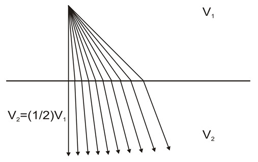
It should be obvious from the above that in order for a wave front to refract, it must strike the velocity boundary at an angle other than 90 degrees. It should also be obvious that in the case of V2 < V1, refraction will be in the opposite direction, and if V1 = V1, no refraction will occur.
Snell's Law quantifies refraction in terms of angle of incidence and velocity contrast. Combining the above diagrams and adding rays,
we can now describe Snell's Law:
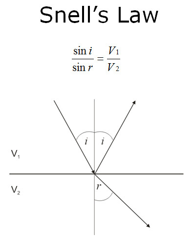
In the figure above, i is the incident angle, and r is the refracted angle, measured between the ray and a line perpendicular to the refracting interface. In the example above, the velocity contrast is positive; V2 > V1. There are numerous derivations of Snell's Law on the web if you wish to understand the math.
From the equation, you can see that for any given positive velocity contrast, as i increases, r increases faster:
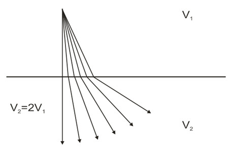
This is important; it is the property of refraction that allows us to use refracted energy to measure subsurface velocities.
Conversely, a negative velocity contrast results in refraction in the opposite direction: